Coal Age Magazine - For more than 100 years, Coal Age has been the magazine that readers can trust for guidance and insight on this important industry.
Issue link: https://coal.epubxp.com/i/1009142
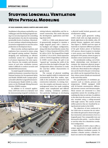
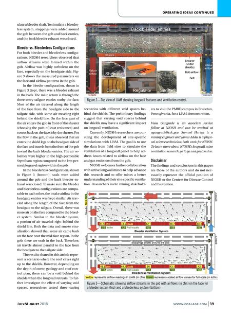
July/August 2018 www.coalage.com 39 operating ideas continued ulate a bleeder shaft. To simulate a bleeder- less system, stoppings were added around the gob between the gob and back entries, and the back bleeder exhaust was closed. Bleeder vs. Bleederless Configurations For both bleeder and bleederless configu- rations, NIOSH researchers observed that airflow streams were formed within the gob. Airflow was highly turbulent on the face, especially on the headgate side. Fig- ure 3 shows the measured parameters on the face and airflow patterns in the gob. In the bleeder configuration, shown in Figure 3 (top), there was a bleeder exhaust in the back. The main return is through the three-entry tailgate entries outby the face. Most of the air traveled along the length of the face from the headgate side to the tailgate side, with some air traveling right behind the shield line. On the face, part of the air enters the gob in front of the shearer (choosing the path of least resistance) and comes back on the face inby the shearer. For the flow in the gob, it was observed that air enters the shield legs on the headgate side of the face and travels from the front of the gob toward the back bleeder entries. The air ve- locities were higher in the high-permeable Styrofoam region compared to the low-per- meable gravel region within the gob. In the bleederless configuration, shown in Figure 3 (bottom), seals were added around the gob and the back bleeder ex- haust was closed. To make sure the bleeder and bleederless configurations are compa- rable to each other, the intake airflow in the headgate entries was kept similar. Air trav- eled along the length of the face from the headgate to the tailgate. Overall, there was more air on the face compared to the bleed- er system. Similar to the bleeder system, a portion of air traveled right behind the shield line. Both the data and smoke visu- alization showed that some air came back on the face near the mid-face region. In the gob, there are seals in the back. Therefore, air travels almost parallel to the face from the headgate to the tailgate side. The results shared in this article repre- sent a scenario where the roof caves right up to the shields. However, depending on the depth of cover, geology and roof con- trol plan, there can be a void behind the shields when the longwall retreats. To fur- ther investigate the effect of varying void spaces, researchers tested three caving scenarios with different void spaces be- hind the shields. The preliminary findings suggest that varying void spaces behind the shields may have a significant impact on longwall ventilation. Currently, NIOSH researchers are pur- suing the development of site-specific simulations with LIAM. The goal is to use the data from field sites to simulate the ventilation of a longwall panel to help ad- dress issues related to airflow on the face and gas emissions from the gob. NIOSH welcomes further collaboration with active longwall mines to help advance this research and to offer mines a better understanding of their site-specific ventila- tion. Researchers invite mining stakehold- ers to visit the PMRD campus in Bruceton, Pennsylvania, for a LIAM demonstration. Vasu Gangrade is an associate service fellow at NIOSH and can be reached at vgangrade@cdc.gov. Samuel Harteis is a mining engineer and James Addis is a physi- cal science technician; both work for NIOSH. To learn more about NIOSH's longwall mine ventilation research, go to go.usa.gov/xnahw. Disclaimer The findings and conclusions in this paper are those of the authors and do not nec- essarily represent the official position of NIOSH or the Centers for Disease Control and Prevention. Figure 2—Top view of LIAM showing longwall features and ventilation control. Figure 3—Schematic showing airflow streams in the gob with airflows (in cfm) on the face for a bleeder system (top) and a bleederless system (bottom).