Coal Age Magazine - For more than 100 years, Coal Age has been the magazine that readers can trust for guidance and insight on this important industry.
Issue link: https://coal.epubxp.com/i/975717
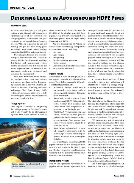
40 www.coalage.com April 2018 operating ideas Detecting Leaks in Aboveground HDPE Pipes by mathew cook No matter the mining and processing op- eration, waste disposal will always be a significant aspect of the operation. The tailings byproduct of mineral or coal pro- cessing is part and parcel of the refinement process. While it is possible to use old workings and pits as a final resting place for tailings, most mines build a tailings storage facility (TSF) or an impoundment. Depending on location and the min- eralogy of the operation, the TSF usually poses a liability. So, all parts of a tailings distribution and management system need to be monitored so that they do not have a negative impact on production, in- frastructure, equipment, personnel, land owners or the environment. Until now, traditional visual inspec- tion methods or inaccurate mass balance instruments have been used to determine pipeline condition; however, with the ad- vances in modern computing and laser technology, Fiber Optic Sensing (FOS) systems are now economical ways of fully automating this process without the need for any services in the field. Tailings Pipelines TSFs require a method of tranporting the tailings slurry to the final location and it will typically be an aboveground pipeline. Due to the abrasive nature of these materials and the requirement for flexibility of the pipeline material, these pipelines are typically constructed of a reinforced plastic, such as High-Density Polyethylene (HDPE). As a pipeline material, HDPE is an ex- cellent candidate for tailings transport due to a number of factors including: • Low cost; • Light weight; • Easy jointing; • Excellent abrasive resistance; • Flexible shape; • Corrosion and Chemical resistance; and • Recyclability/reusability Pipeline Failure Even with all of these advantages, HDPE is not a perfect material and failures still do occur. These failures generally fall under one of four failure methods: • Accidental Damage: failure due to an external energy source such as site equipment impact or damaging earth movement; • Slow Crack Growth: a natural failure mechanism of HDPE. Difficult to de- tect as it occurs from the inside out; strain, stress and temperature ex- tremes are contributing factors; • Rapid Crack Progression: an imposed failure, attributed to high pressure spikes in the fluid either due to block- age, overpressure from pumping sys- tems or water hammer effects from valve shut off; or • Joint Failure: substandard or natu- rally imperfect joints can be a site for thinner pipe sections, which may de- form as above fail as an elastic/plas- tic failure. One of the biggest issues facing HDPE pipeline owners is that existing non-de- struction test methods for HDPE pipes are effectively limited to visual inspection meaning that the pipeline's internal flaws internal cannot be detected. Managing the Problem Due to the significant repercussions of pipeline failure, various operations have attempted to automate leakage detection by more traditional means. In the oil and gas industry, it is possible to monitor pres- sure drop at various locations along the pipe or use a process called mass balance, which measures the total mass (or volume) of material moving past a measured point. However, due to the variable density and hydraulic nature of tailings, fluid pres- sures are not transmitted well along the pipeline. When looking at mass balance, the variances in density pressure and flow rate found in tailings plus the abrasive nature of the material seriously hamper accuracy and leak detection. Any leak de- tection of a leak whose flow is below 5% of total flow is not realistically achievable in the field. A common thread to both of these methods is that neither technology will identify the location of a leakage or rup- ture, only that it has occurred between two sampling points, meaning that leaks could go undiscovered for long periods of time. A Better Solution The ideal solution for this problem is a sys- tem that detects physical effects created by leaks in real time and identifies the precise location of a leak. Fortunately, due to recent advances in modern computing and elec- tronics, this ideal solution is now a reality in the form of distributed FOS systems. FOS systems are able to determine physical effects occurring to a fiber-optic cable over vast distances. These devic- es operate by connecting to a fiber-optic cable and using focused lasers that excite the fiber, so that returning light wave- lengths can shift in response to changes in vibration, temperature and strain in the cable itself. These shifts are detected and their origins are located and analyzed to give a simple digital output that a leak has occurred. It is then handed across to the plant's existing Distributed Control System (DCS) or Supervisory Control and Data Acquisition System (SCADA) alerting the plant operator. All in real time. One of the biggest advantages of FOS systems is that the only in-field compo- Pipeline leakages are extremely costly to a pipeline operator.